12.12 MOD PAGE 1 (VOICE LFO 1)
12. AUDIO TRACK PARAMETERS > 12.12 MOD PAGE 1 (VOICE LFO 1) · PDF p. 60–61 · OS 1.4.1
ERRATUMFADE polarity is stated in reverse between MOD pages
§12.12 (VOICE LFO 1) says positive FADE values “produce a fade-out, while negative values produce a fade-in”; §12.15 (FX LFO 1) and §12.16 (FX LFO 2) print exactly the opposite polarity for the same control. Only one can be right and the manual never says which, so each parameter record repeats the wording of its own section and flags the conflict — unresolved pending hardware.
Adjudicated in AUDIT.md + §12.12
Documented error in the printed manual. This project records contradictions instead of hiding them — the note stays in English, as all source-quoting content does.
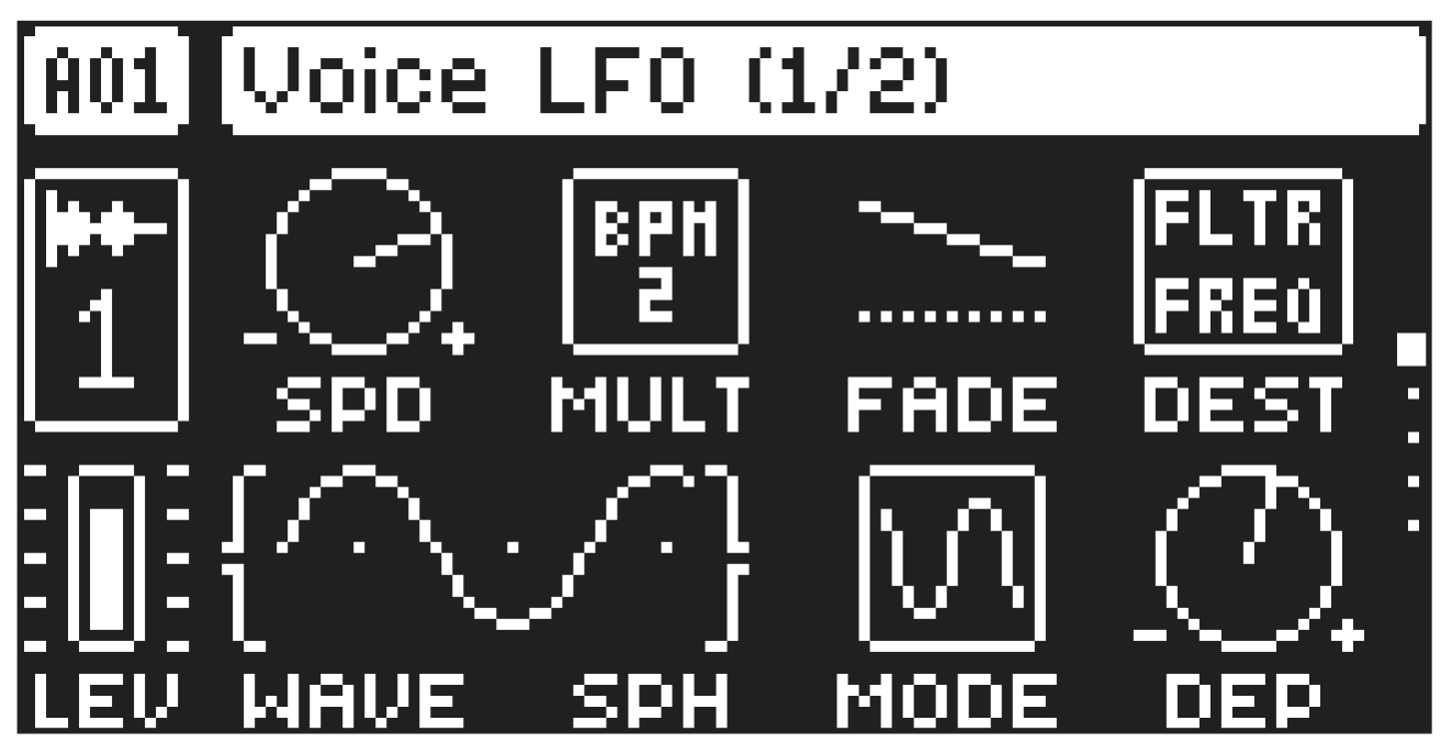
The Voice Low-Frequency Oscillator 1 can be used to modulate the track parameters. Customize the low-frequency oscillator behavior, orientation, speed, and depth on this page. This page controls the behavior of VOICE LFO 1 SPD
Speed sets the speed of the LFO. Try settings of 8, 16 or 32 to sync the LFO to straight beats. The knob is bipolar. The LFO cycle can be played backward by using negative values.
MULT
Multiplier multiplies the SPD parameter by the set factor, either by adjusting the current tempo (BPM settings) or by applying a fixed tempo of 120 BPM.
FADE
Fade In/Out allows for fading in and out of the LFO modulation. The knob is bipolar. Positive values produce a fade-out, while negative values produce a fade-in. 0 gives no fade-in/fade-out. (-64–63) DEST
Destination selects the modulation destination for the LFO. Preview how the LFO modulation will affect the sound by highlighting a destination. Press [YES] to confirm the selection. Press [NO] to cancel and revert to previous selection. For more information, please see “APPENDIX B: LFO/MOD ENVELOPE MODULATION DESTINATIONS” on page 115.
WAVE
Waveform sets the LFO waveform. The Triangle, Sine, Square, Sawtooth, and Random waveforms are bipolar. The Exponential and Ramp are unipolar.
SPH
Start Phase sets the point within the wave cycle where the LFO will start when it is trigged. 0 makes the LFO start at the beginning of a complete wave cycle, 64 makes it start at the center. A small square at the start of the waveform shows that the wave cycle begins at a zero-crossing. If WAV is set to RND then the SPH parameter changes to SLEW and adds slew to the transitions in the waveform.
MODE
Trig Mode determines how the LFO behaves when a note is triggered.
- FREE is the default free-running mode. It makes the LFO run continuously, never restarting or stopping even if notes are trigged.
- TRIG makes the LFO restart when a note is trigged.
- HOLD makes the LFO run free in the background, but when a note is trigged, the LFO output level is latched and held still until the next note is trigged.
- ONE The LFO starts when a note is trigged, then runs to the end of the waveform and then stops.
This makes the LFO function similar to an envelope.
- HALF The LFO starts when a note is trigged, then runs to the middle of the waveform and then stops.
DEP
Depth sets the depth and polarity of the LFO modulation. Both negative and positive modulation depths are possible. A center setting, 0.00, equals no modulation depth.