A.3 FX MACHINES
APPENDIX A: MACHINES > A.3 FX MACHINES · PDF p. 100–115 · OS 1.4.1
The FX machines can be added at several locations in the signal path. However, not all FX machines can be used in every location. The following is a description of the machines that can be added to each track type.
INSERT EFFECTS (Two FX slots per track. Track 1–8)
- Bypass (“A.3.1 BYPASS” on page 101)
- Chrono Pitch (“A.3.2 CHRONO PITCH” on page 101)
- Comb ± Filter (“A.3.3 COMB ± FILTER” on page 102)
- Compressor (“A.3.4 COMPRESSOR” on page 102)
- Daisy Delay (“A.3.5 DAISY DELAY” on page 104)
- Degrader (“A.3.6 DEGRADER” on page 104)
- Dirtshaper (“A.3.7 DIRTSHAPER” on page 105)
- Filter Folder (“A.3.8 FILTER FOLDER” on page 106)
- Filterbank (“A.3.9 FILTERBANK” on page 106)
- Frequency Warper (“A.3.10 FREQUENCY WARPER” on page 107)
- Infinite Flanger (“A.3.11 INFINITE FLANGER” on page 108)
- Low-pass Filter (“A.3.12 LOW-PASS FILTER” on page 108)
- Panoramic Chorus (“A.3.14 PANORAMIC CHORUS” on page 109)
- Phase 98 (“A.3.15 PHASE 98” on page 110)
- Saturator Delay (“A.3.17 SATURATOR DELAY” on page 111)
BUS EFFECTS (Two FX slots per track. Track 9–12)
- Bypass (“A.3.1 BYPASS” on page 101)
- Chrono Pitch (“A.3.2 CHRONO PITCH” on page 101)
- Comb ± Filter (“A.3.3 COMB ± FILTER” on page 102)
- Compressor (“A.3.4 COMPRESSOR” on page 102)
- Daisy Delay (“A.3.5 DAISY DELAY” on page 104)
- Degrader (“A.3.6 DEGRADER” on page 104)
- Dirtshaper (“A.3.7 DIRTSHAPER” on page 105)
- Filter Folder (“A.3.8 FILTER FOLDER” on page 106)
- Filterbank (“A.3.9 FILTERBANK” on page 106)
- Frequency Warper (“A.3.10 FREQUENCY WARPER” on page 107)
- Infinite Flanger (“A.3.11 INFINITE FLANGER” on page 108)
- Low-pass Filter (“A.3.12 LOW-PASS FILTER” on page 108)
- Panoramic Chorus (“A.3.14 PANORAMIC CHORUS” on page 109)
- Phase 98 (“A.3.15 PHASE 98” on page 110)
- Saturator Delay (“A.3.17 SATURATOR DELAY” on page 111)
- Steel Box Reverb (“A.3.18 STEEL BOX REVERB” on page 112)
- Supervoid Reverb (“A.3.19 SUPERVOID REVERB” on page 113)
- Warble (“A.3.20 WARBLE” on page 114)
SEND EFFECTS (One FX slot per track. Track 13–15)
- Bypass (“A.3.1 BYPASS” on page 101)
- Compressor (“A.3.4 COMPRESSOR” on page 102)
- Daisy Delay (“A.3.5 DAISY DELAY” on page 104)
- Filter Folder (“A.3.8 FILTER FOLDER” on page 106)
- Panoramic Chorus (“A.3.14 PANORAMIC CHORUS” on page 109)
- Rumsklang Reverb (“A.3.16 RUMSKLANG REVERB” on page 110)
- Saturator Delay (“A.3.17 SATURATOR DELAY” on page 111)
- Steel Box Reverb (“A.3.18 STEEL BOX REVERB” on page 112)
- Supervoid Reverb (“A.3.19 SUPERVOID REVERB” on page 113)
MIX EFFECTS (One FX slot. Track 16)
- Bypass (“A.3.1 BYPASS” on page 101)
- Chrono Pitch (“A.3.2 CHRONO PITCH” on page 101)
- Comb ± Filter (“A.3.3 COMB ± FILTER” on page 102)
- Compressor (“A.3.4 COMPRESSOR” on page 102)
- Daisy Delay (“A.3.5 DAISY DELAY” on page 104)
- Degrader (“A.3.6 DEGRADER” on page 104)
- Dirtshaper (“A.3.7 DIRTSHAPER” on page 105)
- Filterbank (“A.3.9 FILTERBANK” on page 106)
- Frequency Warper (“A.3.10 FREQUENCY WARPER” on page 107)
- Infinite Flanger (“A.3.11 INFINITE FLANGER” on page 108)
- Low-pass Filter (“A.3.12 LOW-PASS FILTER” on page 108)
- Multimode Filter (“A.3.13 MULTIMODE FILTER” on page 109)
- Panoramic Chorus (“A.3.14 PANORAMIC CHORUS” on page 109)
- Phase 98 (“A.3.15 PHASE 98” on page 110)
- Saturator Delay (“A.3.17 SATURATOR DELAY” on page 111)
- Steel Box Reverb (“A.3.18 STEEL BOX REVERB” on page 112)
- Supervoid Reverb (“A.3.19 SUPERVOID REVERB” on page 113)
- Warble (“A.3.20 WARBLE” on page 114)
A.3.1 BYPASS
This machine lets the signal bypass the selected machine slot.
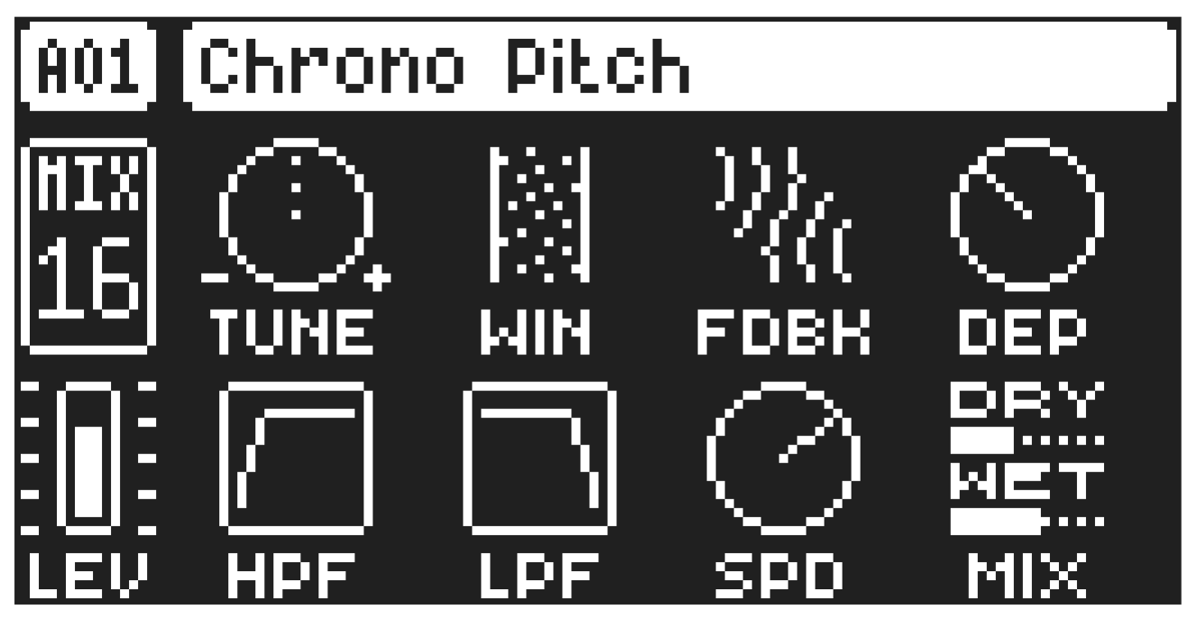
A.3.2 CHRONO PITCH
A granular pitch shifter with modulation and feedback.
TUNE
Adjusts the pitch (measured in semitones).
WIN
Window controls the window (grain) size.
FDBK
Feedback introduces feedback.
DEP
LFO Depth controls the amount of pitch modulation applied from the built-in LFO.
HPF
High-Pass Filter applies a high-pass filter to the wet signal.
LPF
Low-Pass Filter applies a low-pass filter to the wet signal.
SPD
LFO Speed changes the speed of the built-in LFO..
MIX
Dry/Wet sets the mix between the dry signal and the affected signal.
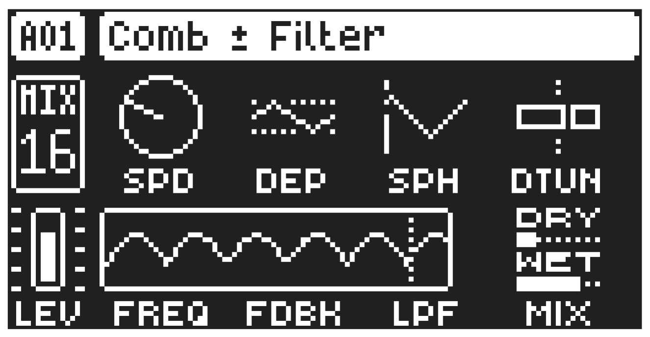
A.3.3 COMB ± FILTER
This stereo comb filter with built-in modulation introduces metallic sounding, pitch-tuned, resonant overtones.
SPD
Modulation Speed controls the frequency of a built-in triangle LFO. It is tempo-synced and the values are measured in sequencer steps.
DEP
Modulation Depth controls the amount of frequency modulation applied from the LFO to the comb filter.
SPH
LFO Start Phase controls the triggering behavior of the LFO. The parameter value OFF indicates that it will run free. Other values will cause the LFO to retrigger from that phase position every time a note is played on the track.
DTUN
Detune offsets the frequency of the comb filter in the left and right channels.
FREQ
Frequency sets the resonant frequencies of the comb filter. It can be set to both positive and negative values.
FDBK
Feedback sets the gain of the feedback signal. Positive parameter values results in positive feedback and produces a string-like sound. Negative values results in negative feedback and produces a more hollow, tube-like sound. Please be aware that setting FDBK to extreme values can create a very loud sound.
LPF
Low-pass Filter sets the cutoff frequency of the low-pass filter in the feedback signal.
MIX
Dry/Wet sets the mix between the dry signal and the affected signal.
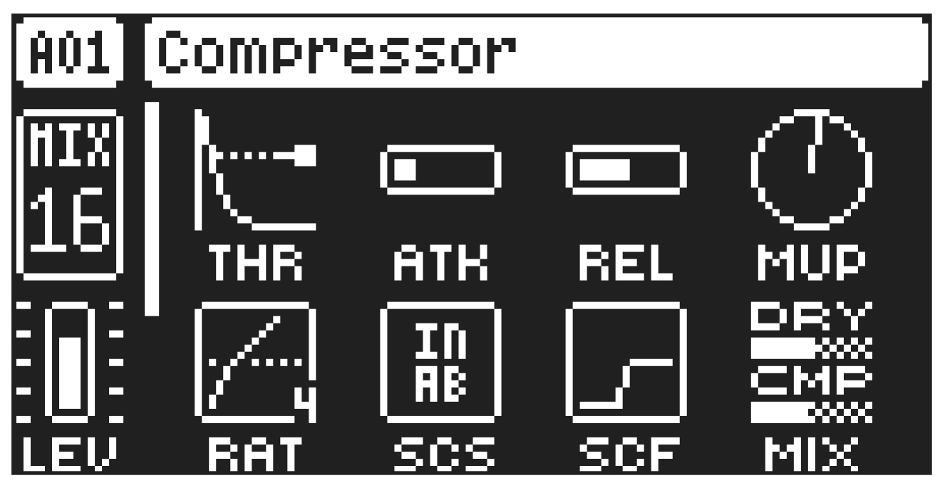
A.3.4 COMPRESSOR
The compressor effect compresses the dynamic range of the signal by reducing the volume of loud sounds relative to the quiet sounds. The gain reduction amount is shown with a bar next to the THR and RAT parameters.
THR
Threshold sets the threshold of the compressor. A lower threshold means a larger portion of the signal is subject to compression.
ATK
Attack Time sets the time of the compressor attack phase, i.e., how quickly the compressor responds to loud peaks.
REL
Release Time sets the duration of the compressor’s release phase, i.e., how long it takes for the compression to recover during quieter moments MUP
Makeup Gain sets the makeup gain of the compressor output to compensate for the reduced signal levels caused by compression. The Makeup Gain parameter value is displayed in dB.
RAT
Compression Ratio. There are eight different compression ratios: 1.50, 2.00, 3.00, 4.00, 6.00, 8.00, 16.00, and 20.00. Higher ratios result in greater signal compression.
SCS
Sidechain Source decides what audio source the compressor analyzes when it performs sidechaining.
Sidechaining is the process when the compressor uses the output of an audio source to control the overall action of the compressor. For example, if you set SCS to TRK1 where you have a kick drum, every time the kick drum plays, the compressor lowers the overall sound of the mix. This parameter is only available when the compressor is used on the Bus or Mix tracks.
MAIN sets the sidechain source to be the audio sent to the Main (L/R) outputs.
TRK1–8 sets the sidechain source to be the audio sent from one of the separate audio tracks.
BUS1–4 sets the sidechain source to be the audio sent from one of the Bus tracks. (Only available on the Mix track.)
BUS IN: 1–4 sets the sidechain source to be the audio coming in to one of the Bus tracks. (Only available on the Bus tracks.)
IN A sets the sidechain source to be the audio coming from INPUT A.
IN B sets the sidechain source to be the audio coming from INPUT B.
IN AB sets the sidechain source to be the audio coming from INPUT A and B.
SCF
Sidechain Filter filters the signal from the sidechain source before the compressor analyzes it. The parameter ranges from a low-pass filter to a high-pass filter. Negative parameter values set a low-pass filter. Positive parameter values set a high-pass filter.
When set as a low-pass filter, the compressor reacts mostly to bass frequencies. Use this setting for a characteristic pumping compressor sound. When set as a high-pass filter, the compressor reacts less to bass frequencies. Use this setting to avoid pumping.
MIX
Mix sets the mix of the uncompressed signal and the compressor output signal. A setting of 0 results in a completely uncompressed signal. A setting of 127 lets only the compressed signal pass through.
All values in between mix the uncompressed signal with the compressed signal, which is known as parallel compression.
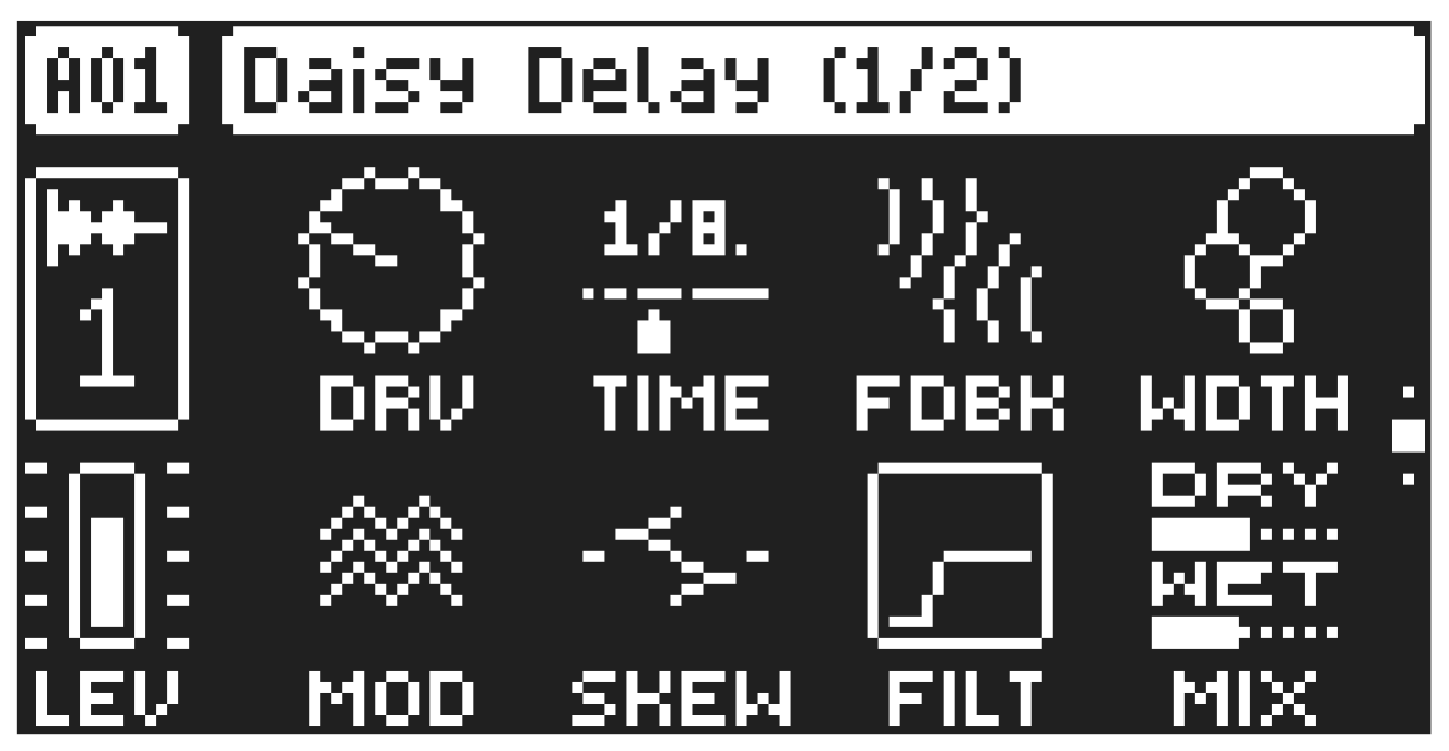
A.3.5 DAISY DELAY
A delay effect with more control over the stereo image and evolution over time.
DRV
Drive controls the amount of saturation applied to the delay’s input.
TIME
Delay Time Division controls the base repeat time.
FDBK
Feedback adjusts the amount of delay output fed back into its input.
WIDH
Width adjusts the panning of the input and feedback signals before being mixed.
MOD
Modulation applies an internal modulator to the delay time.
SKEW
Skew scales the relative delay times in the left and right channels so that they interact rhythmically.
FILT
Applies a tilt filter to the delayed signal - to the left, it low-passes the signal, and to the right, it high-passes.
MIX
Dry/Wet sets the mix between the dry and affected signals. This parameter is not available if the effect is used on a Send FX track.
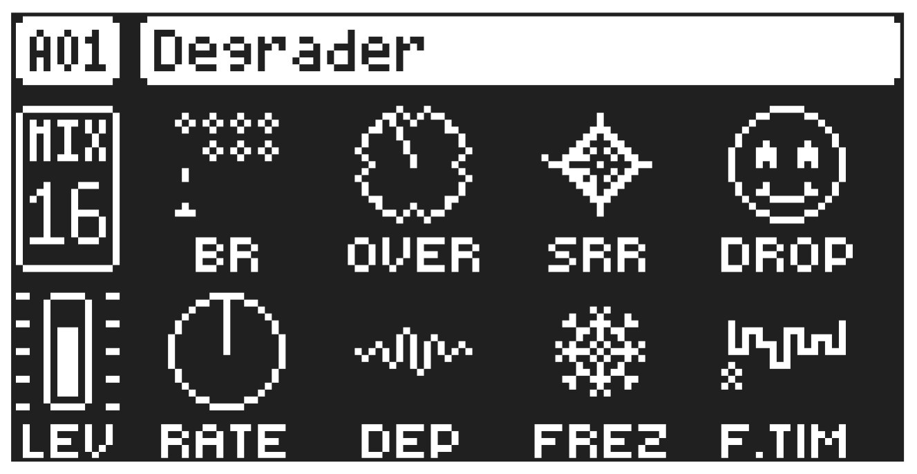
A.3.6 DEGRADER
A collection of lo-fi effects.
BR
Bit Reduction sets the bit rate. The parameter range is from 16 bits to 1 bit.
OVER
Overdrive sets the gain amount into an overdrive.
SRR
Sample Rate Redux sets the amount of sample rate reduction.
DROP
Drop-outs introduce randomly placed drop-outs into the audio signal. Higher values increase the frequency and the duration of the drop-outs.
RATE
Modulation Rate sets the frequency of a modulation sine oscillator.
DEP
Modulation Depth introduces ring modulation with the modulator oscillator, increasing in intensity.
FREZ
Freeze introduces randomly-placed stutters into the signal.
F.TIM
Freeze Time sets the length of the stutters introduced by the FREZ parameter. The value RAND causes a random length to be picked each time. The other values are measured in sequencer steps.
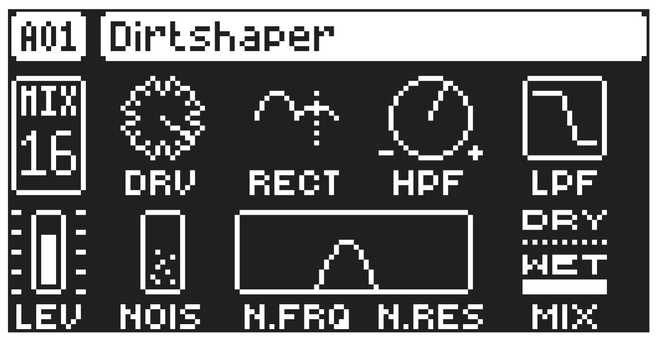
A.3.7 DIRTSHAPER
Adds distortion and grit.
DRV
Drive adds overdrive distortion.
RECT
Rectify blends between the driven signal and a full-wave rectified version of it.
HPF
High-pass filter is a bipolar control that controls two different high-pass filters. To the left, the input is high-pass filtered before the distortion. To the right, it is high-pass filtered after the rectifier.
LPF
Low-pass filter applies a low-pass filter to the output.
NOIS
Noise introduces a noise signal ring-modulated with the distorted input.
N.FRQ
Noise Frequency applies a low-pass filter to the noise signal.
N.RES
Noise Resonance adjusts the resonance of the noise filter.
MIX
Dry/Wet sets the mix between the dry signal and the affected signal.
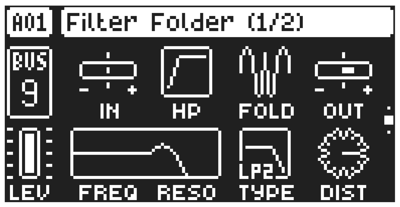
A.3.8 FILTER FOLDER
The Filter Folder is an effect that pairs a wavefolder with two added filters to help shape the sound. Wavefolding increases the wave’s complexity, creating a more overtone-rich sound. The signal flow in the effect is as follows: Input level > High-pass filter > Wavefolder > Multimode filter > Dist > Output level.
ILEV
Input Level boosts or attenuates the level at the FX input.
HP
High Pass filters the sound before the wavefolder.
FOLD
Folder sets the amount of wavefolding of the sound.
OLEV
Output Level boosts or attenuates the level out from the FX.
FREQ
Frequency sets the cutoff frequency of the Multimode filter
RESO
Resonance sets the Multimode filter’s resonance behavior. Resonance introduces a peak in the spectrum at the cutoff frequency.
TYPE
Filter Type sets the Multimode filter’s type. Low-pass 4, Low-pass 2, Band-pass 2, High-pass 2, Low-pass notch, Notch 1, Notch 2, Off.
DIST
Post Dist sets the amount of distortion/overdrive applied to the sound after the Multimode filter.
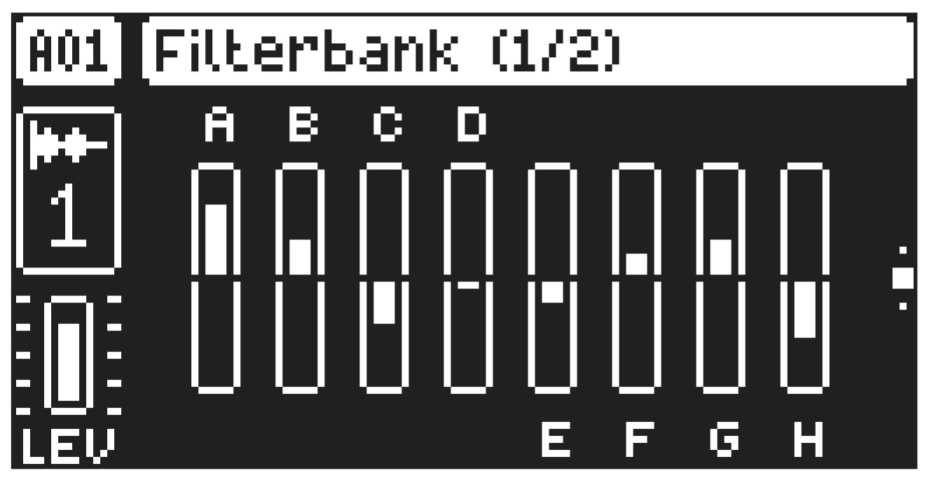
A.3.9 FILTERBANK
An eight-band fixed filter bank.
A
Gain A sets the gain of a low-pass filter at 90 Hz.
B
Gain B sets the gain of a band-pass filter at 121.9 Hz.
C
Gain C sets the gain of a band-pass filter at 224.8 Hz.
D
Gain D sets the gain of a band-pass filter at 418.0 Hz.
E
Gain E sets the gain of a band-pass filter at 777.4 Hz.
F
Gain F sets the gain of a band-pass filter at 1445.8 Hz.
G
Gain G sets the gain of a band-pass filter at 2688.6 Hz.
H
Gain H sets the gain of a high-pass filter at 4 kHz.
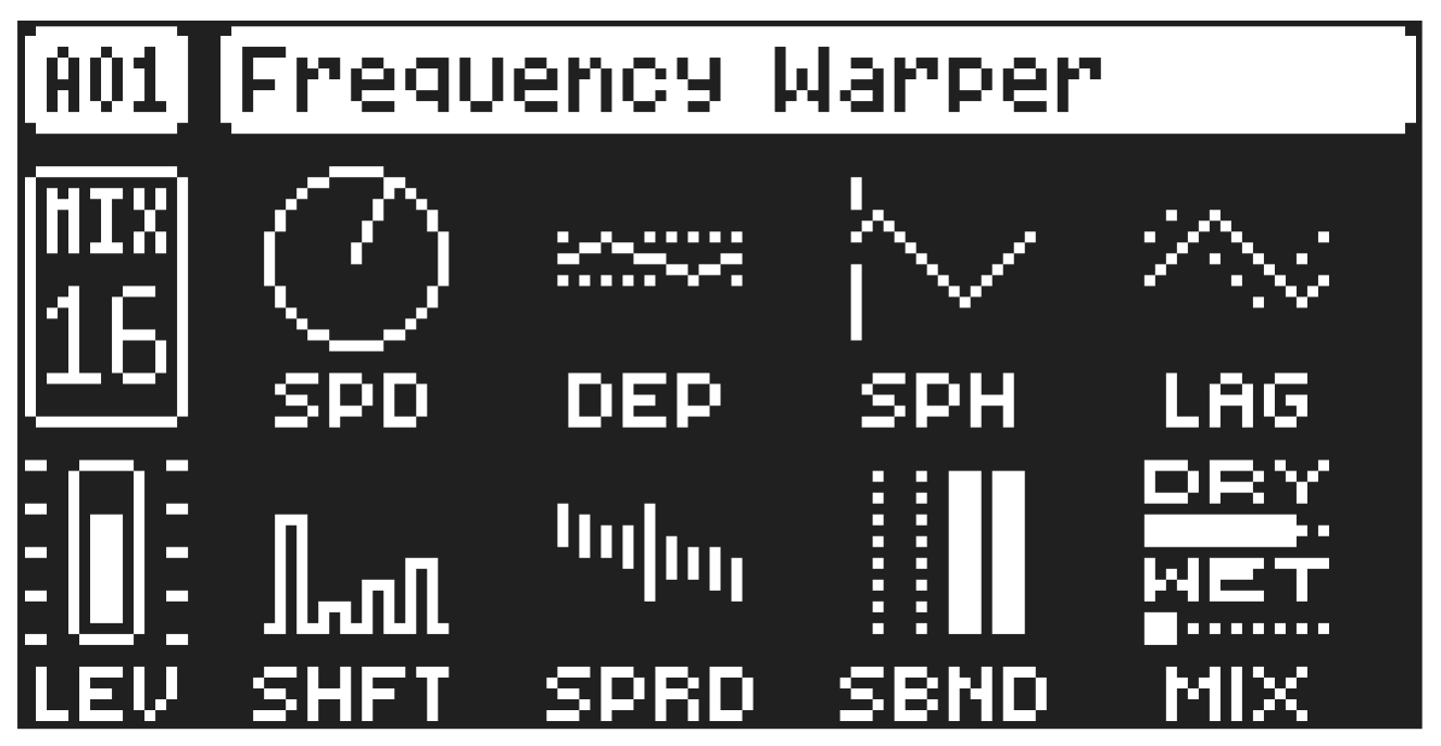
A.3.10 FREQUENCY WARPER
A frequency-shifting effect in the style of vintage analog effects.
SPD
LFO Speed sets the speed of the built-in LFO.
DEP
LFO Depth controls the amount of frequency modulation applied from the LFO to the shifter.
SPH
LFO Start Phase controls the triggering behavior of the LFO. The value “OFF” indicates that it will run free. Other values will cause the LFO to retrigger from that phase position every time a note is played on the track.
LAG
LFO Phase Offset offsets the LFO’s phase position in the left and right channels.
SHFT
Shift Amount controls the shift distance.
SPRD
Stereo Spread offsets the shift distance in the left and right channels.
SBND
Sideband blends between the frequency shifter’s output and an alternate output signal with different characteristics.
MIX
Dry/Wet sets the mix between the dry signal and the affected signal..
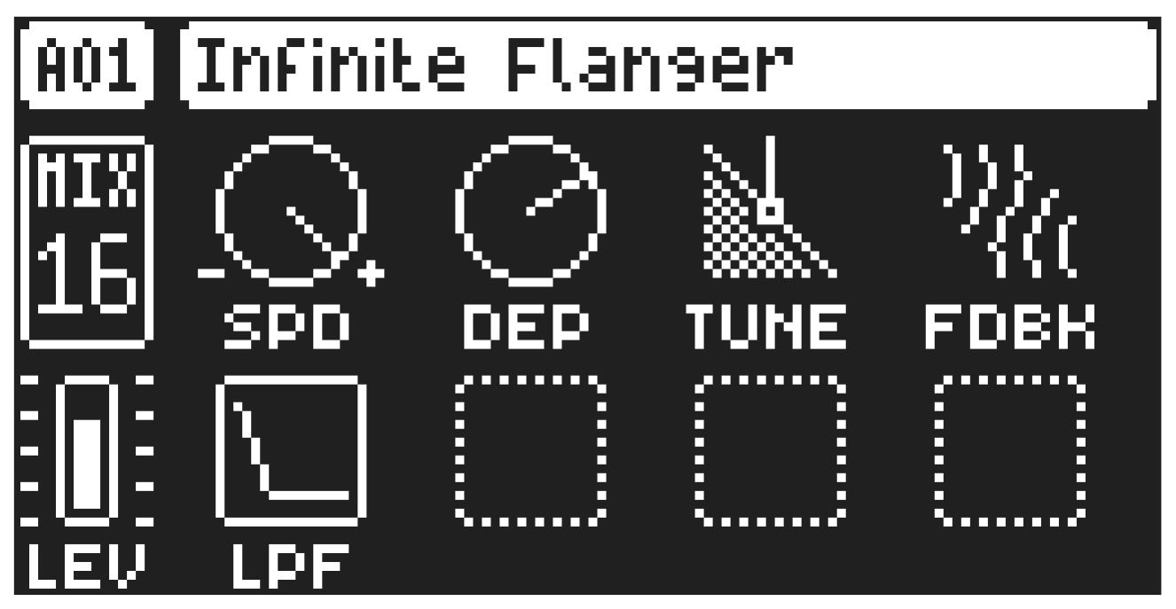
A.3.11 INFINITE FLANGER
This is a flanger with barber-pole motion, meaning it sounds like it rises or falls continuously without ever reversing.
SPD
Speed sets the speed of the pitch motion. A parameter value of 0 gives a constant pitch, negative values result in increasingly quick downward motions, and positive values result in increasingly quick upward motions.
DEP
Depth sets the intensity of the flanging effect.
TUNE
Downtune adjusts the tuning of the delay line progressively downward, from true flanging to sounds that resemble comb filtering, and finally to audible delay.
FDBK
Feedback sets the amount of output signal fed back into the delay line.
LPF
Feedback Filter Cutoff sets the cutoff frequency of a low-pass filter placed in the feedback loop.
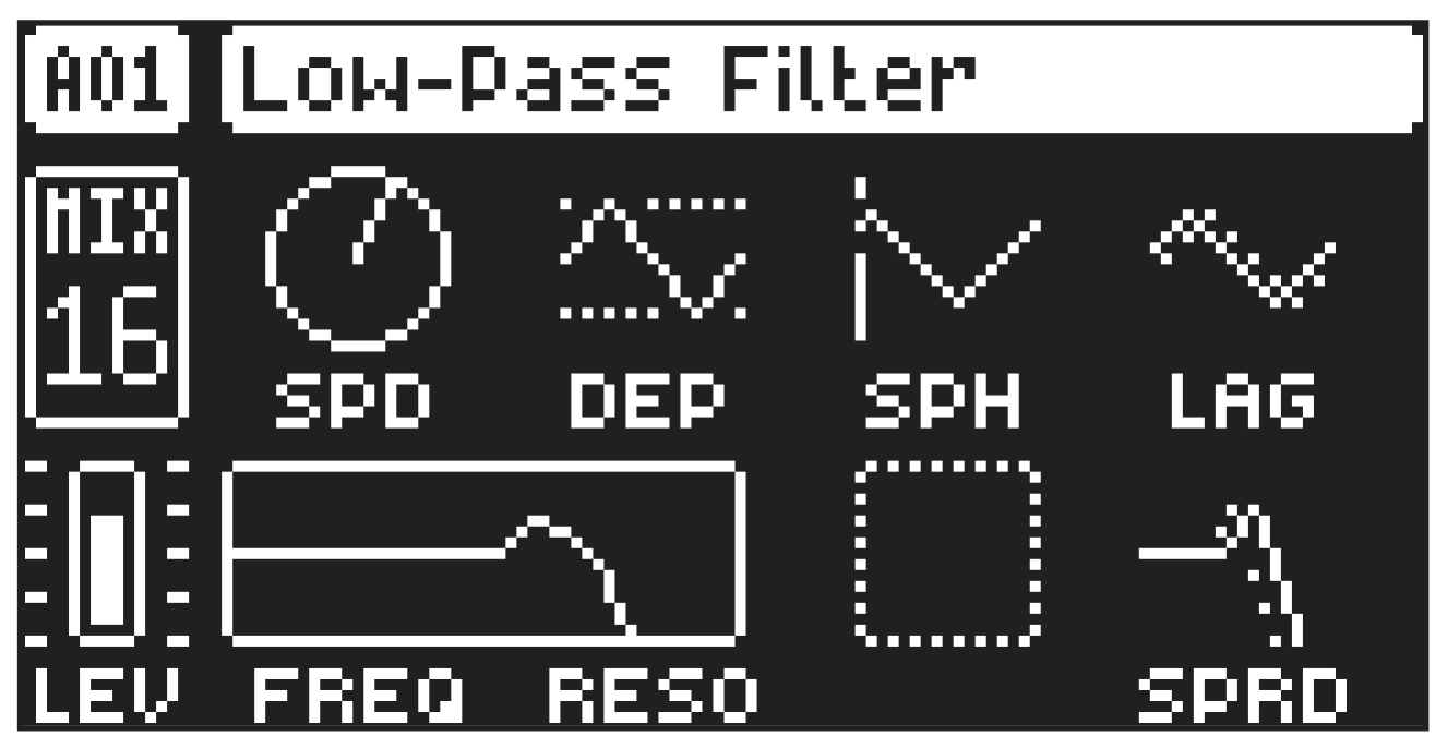
A.3.12 LOW-PASS FILTER
This is a 4-pole, 24 dB/octave slope low-pass filter with internal modulation and stereo width controls.
SPD
LFO Speed sets the speed of the built-in LFO. It is tempo-synced, and the values are measured in sequencer steps.
DEP
LFO Depth sets the amount of frequency modulation applied from the LFO to the filter.
SPH
LFO Start Phase sets the triggering behavior of the LFO. The parameter value OFF indicates that it will run free. Other values will cause the LFO to retrigger from that phase position every time a note is played on the track.
LAG
LFO Phase Offset offsets the LFO’s phase in the right and left channels.
FREQ
Cutoff Frequency sets the cutoff frequency of the filter.
RESO
Resonance sets the resonance behavior of the filter. Resonance introduces a peak in the spectrum at the cutoff frequency.
SPRD
Stereo Spread offsets the filter cutoff frequency in the left and right channels.
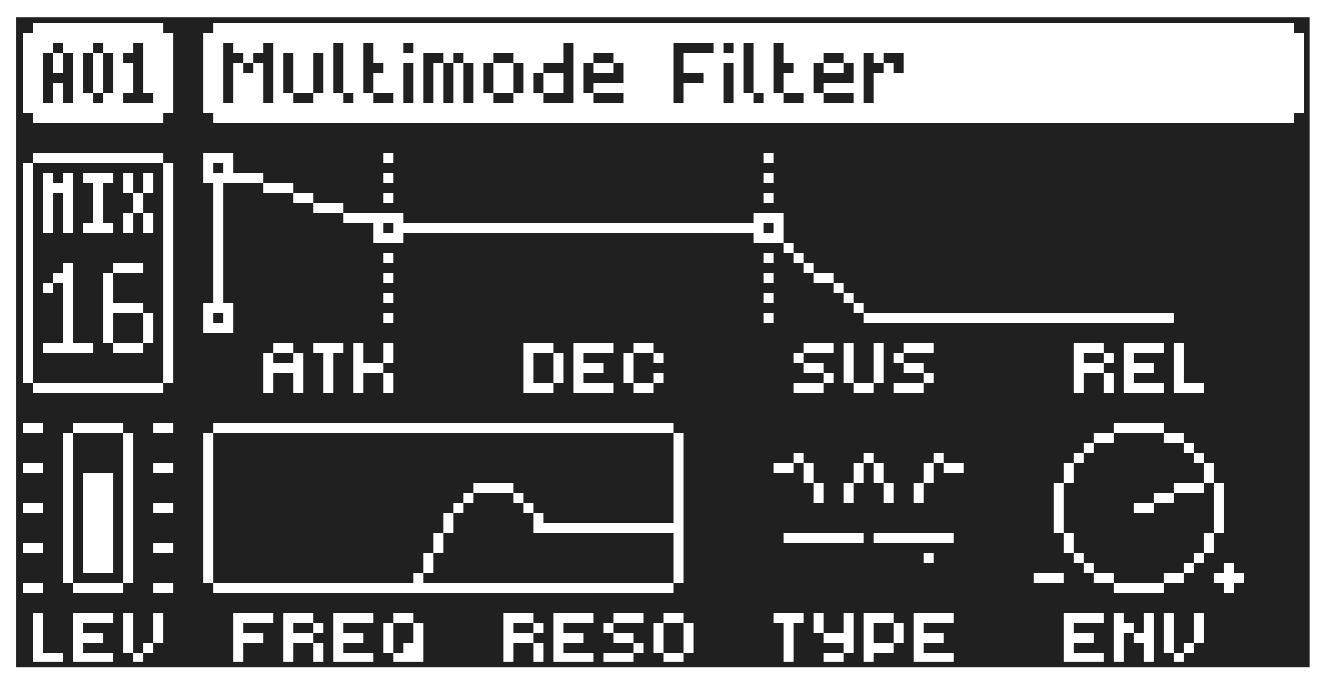
A.3.13 MULTIMODE FILTER
This filter lets you morph from a Low-pass to a Band-pass to a High-pass filter.
ATK
Attack Time sets the length of the attack phase of the filter envelope.
DEC
Decay Time sets the length of the decay phase of the filter envelope.
SUS
Sustain Level sets the sustain level of the filter envelope.
REL
Release Time sets the length of the release phase of the filter envelope.
FREQ
Frequency sets the cutoff frequency of the Multimode filter.
RESO
Resonance sets the resonance behavior of the filter. Resonance introduces a peak in the spectrum at the cutoff frequency.
TYPE
Type morphs the Multimode filter from low-pass to band-pass to high-pass.
ENV
Env. Depth sets the amount of cutoff frequency modulation from the filter envelope. The knob is bipolar, both negative and positive modulation depths are available.
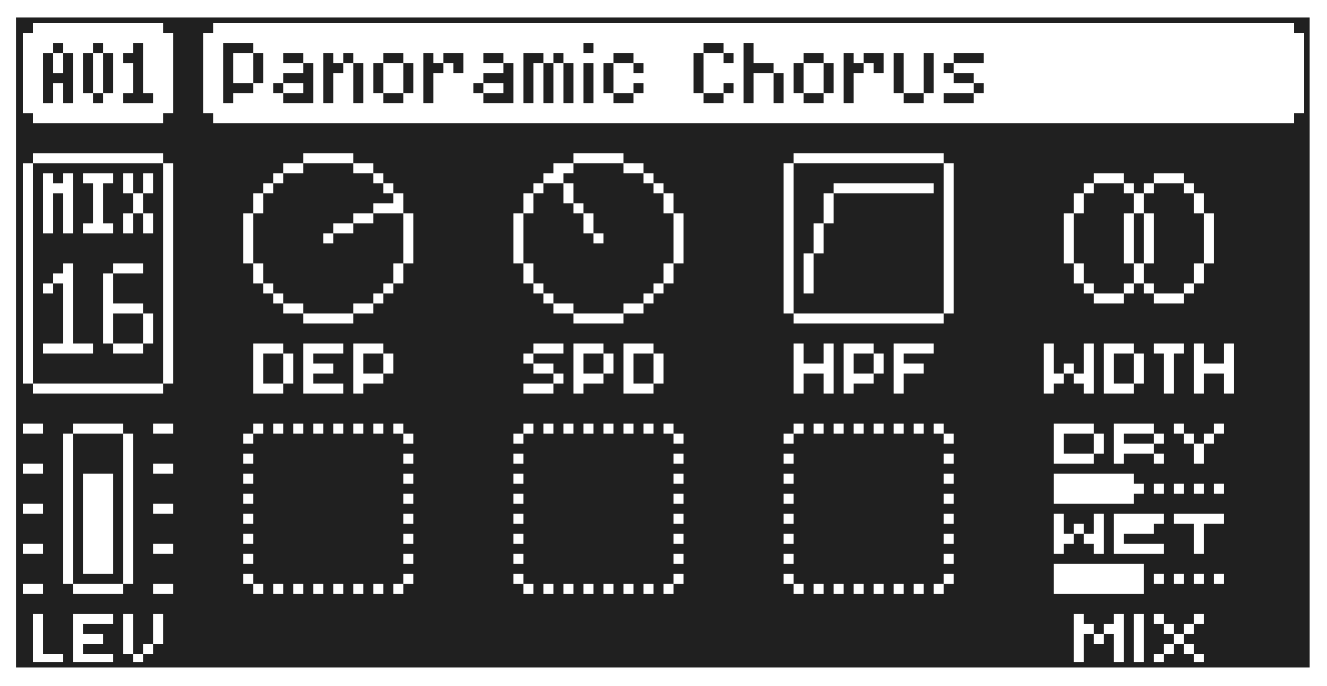
A.3.14 PANORAMIC CHORUS
The chorus are used to widen the sound, enhance the stereo image, or add subtle movement to sounds.
DEP
Depth sets the depth of the LFO modulation of the chorus.
SPD
Speed sets the speed of the LFO modulation of the chorus.
HPF
High-pass sets the high-pass filtering of the input signal.
WDTH
Width sets the stereo width of the chorus.
MIX
Dry/Wet sets the mix between the dry signal and the affected signal. This parameter is not available if the effect is used on a Send FX track.
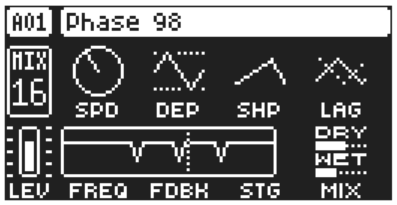
A.3.15 PHASE 98
A phaser that can blend between four- and six-stage versions.
SPD
LFO Speed sets the speed of the built-in LFO.
DEP
LFO Depth sets the amount of frequency modulation applied from the LFO to the phaser.
SHP
LFO Shape sets the wave shape of the LFO. It smoothly transitions from a descending ramp to a triangle and then to an ascending ramp.
LAG
LFO Phase Offset adjusts the phase of the built-in LFO in the right and left channels.
FREQ
Cutoff Frequency sets the center frequency of the phaser.
FDBK
Phaser Feedback sets the feedback (resonance) of the phaser.
STG
Stage Mix blends between the four-stage and six-stage phaser outputs.
MIX
Dry/Wet sets the mix between the dry signal and the affected signal.
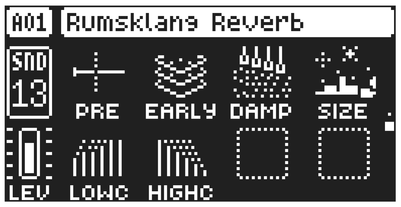
A.3.16 RUMSKLANG REVERB
The Rumsklang Reverb effect controls the persistence, and ambient characteristics, of the sound reverberations. It focuses mainly on simulating large spaces.
PRE
Pre-delay sets the pre-delay time of the reverb.
EARLY
Early Reflections sets the amount of early room reflections in the reverb.
DAMP
Damping determines how quickly the high-end frequencies of the reverb tail fade out, influencing the overall brightness or darkness of the reverb sound.
SIZE
Size sets the length of the decay phase of the reverberated signal, essentially setting the size of the simulated acoustic space.
LOWC
Lowcut sets the cutoff frequency of the reverbs low-pass filter.
HIGHC
HPF sets the cutoff frequency of the reverbs high-pass filter.
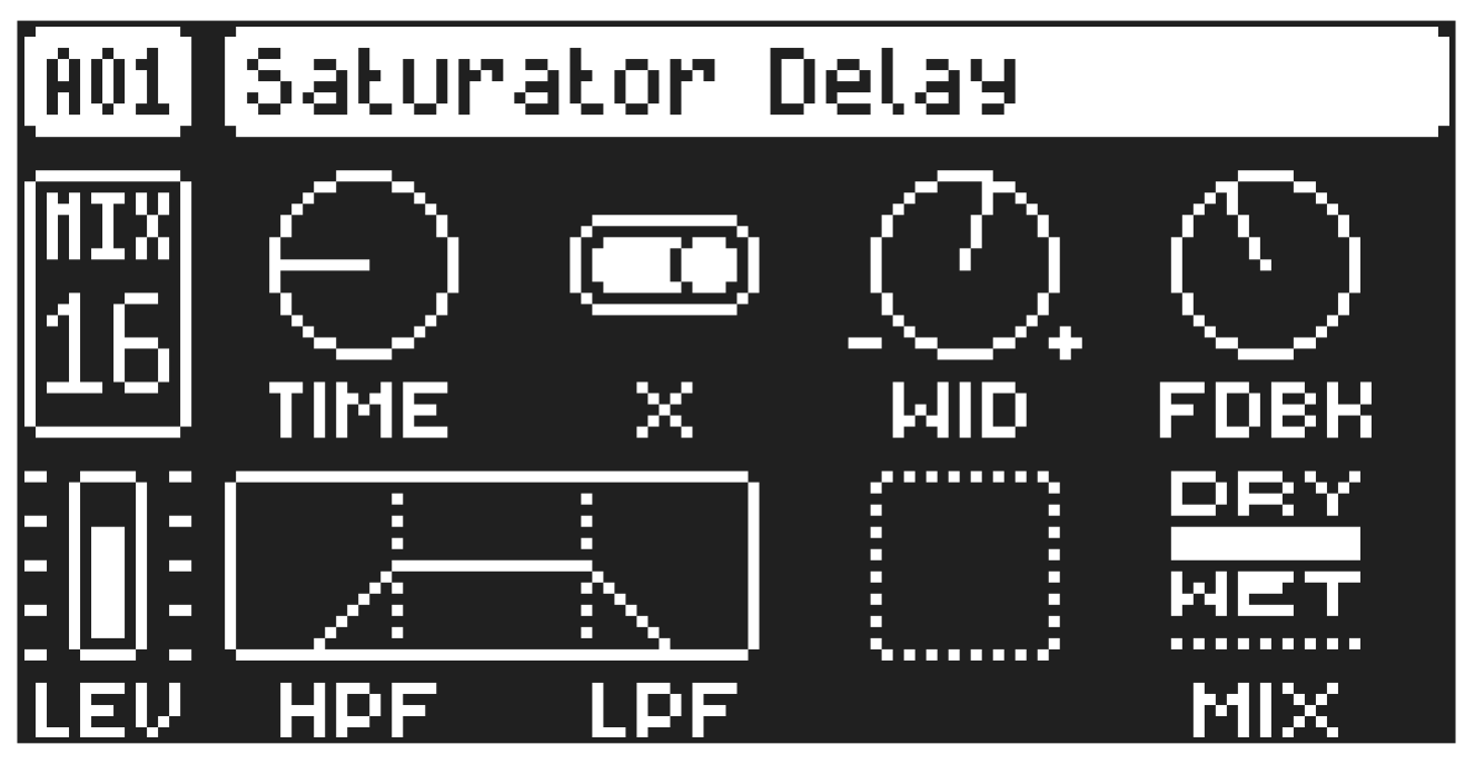
A.3.17 SATURATOR DELAY
The Saturator Delay effect takes the input signal, delays it in time and then rejoins it with the original signal.
TIME
Delay Time sets the delay time. It is relative to the current BPM and is measured in 128th notes.
TIME setting
Divide ratio
1/128
1/64
2.67
1/48 (1/32T)
1/64.
1/32
5.33
1/24 (1/16T)
1/32.
1/16
10.67
1/12 (1/8T)
1/16.
TIME setting
Divide ratio
1/8
21.33
1/6 (1/4T)
1/8.
1/4
42.67
1/3 (1/2T)
1/4.
1/2
1/2.
X
Ping Pong sets the delay signal to alternate across the stereo field. There are two settings:
- OFF lets you manually set the position of the delay signal in the stereo field. Use the WID parameter to change the stereo field position.
- ON makes the delay signal alternate between left and right pan positions. The WID parameter controls the amount of panning.
WID
Stereo Width sets the delay signal pan width across the stereo field. The knob is bipolar.
FDBK
Feedback Gain sets the amount of delay output signal to feed back into the input of the delay. With higher parameter settings, infinite and/or swelling delays are possible. Please be aware that high feedback can lead to a very loud signal.
HPF
High-pass Filter sets the cutoff frequency of the delay high-pass filter.
LPF
Low-pass Filter sets the cutoff frequency of the delay low-pass filter.
MIX
Dry/Wet sets the mix between the dry and affected signals. This parameter is not available if the effect is used on a Send FX track.
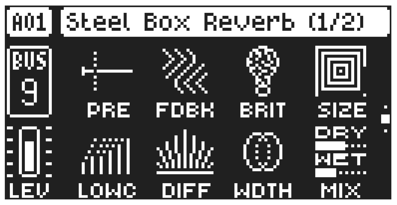
A.3.18 STEEL BOX REVERB
The Steel Box reverb is a character reverb inspired by early digital reverbs and ‘90s plate reverbs. It has wide parameter ranges by design to achieve sonically wide results.
SIZE
Sets the size of the steel box reverbator.
FDBK
Feedback sets the amount of feedback inside the delay tank. High numbers cause a longer decay, but it also depends on the brightness and low cut settings.
BRIT
Brightness controls the damping as well as filtering in the feedback path.
PRE
Predelay sets the predelay time before sound goes into the reverb.
WDTH
Width controls the stereo width of the tapped output audio.
DIFF
Diffuse sets the amount of diffusion applied to the input sound before it enters the reverb tank.
LOWC
Low Cut the amount of low-cut filter inside the feedback path of the reverb tank.
MIX
Dry/Wet sets the mix between the dry and affected signals. This parameter is not available if the effect is used on a Send FX track.
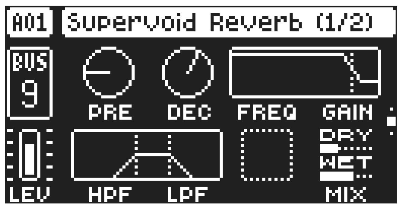
A.3.19 SUPERVOID REVERB
The Supervoid Reverb effect controls the persistence, and ambient characteristics, of the sound reverberations. It can simulate many different sonic locations, from huge spaces to small rooms.
PRE
Pre-delay sets the pre-delay time of the reverb.
DEC
Decay Time sets the length of the decay phase of the reverberated signal, essentially setting the size of the simulated acoustic space.
FREQ
FB Shelving Freq sets the shelving filter frequency. Together with the GAIN parameter, it can be used to dampen the reverberated signal above a chosen frequency, making the reverberation sound more prominent or more muffled.
GAIN
FB Shelving Gain affects the damping of the reverberated signal above the shelving frequency set by the FREQ parameter. At max value the treble is included in the reverberations; lowering the value gradually dampens it.
HPF
HPF sets the cutoff frequency of the reverb high-pass filter that affects the audio going into the reverb.
LPF
LPF sets the cutoff frequency of the reverb low-pass filter that affects the audio going into the reverb.
MIX
Dry/Wet sets the mix between the dry signal and the affected signal. This parameter is only available if the effect is used on a Bus track or the Mix track.
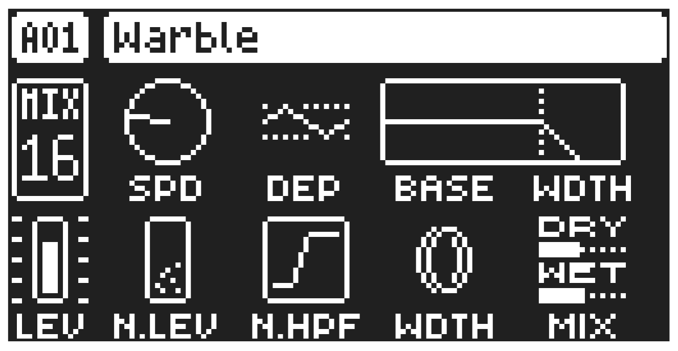
A.3.20 WARBLE
The Warble effect helps you recreate a sound similar to that of an old tape recorder by adding a pitch warble effect, along with audio and noise filtering.
SPEED
Sets the speed of the warble effect: A setting of 0 makes the speed random.
DEPTH
Sets the depth of the warble effect.
BASE
Sets the base frequency of the filter.
WIDTH
Sets the frequency width above the base frequency.
N.LEV
Noise Level sets the amount of noise that is added to the effect. Please note that the noise level is not affected by the MIX setting.
N.HPF
High-pass filter sets the frequency for the high-pass filtering of the noise.
STEREO
Stereo Width sets the amount of the warble effect in the stereo field.
MIX
Dry/Wet sets the mix between the dry signal and the affected signal.
APPENDIX B: LFO/MOD ENVELOPE MODULATION DESTINATIONS
APPENDIX B: LFO/MOD ENVELOPE MODULATION DESTINATIONS
The following are the modulation destinations for Tonverk’s LFOs and Modulation envelope. The Voice LFOs and Modulation envelope modulate parameters on all parameter pages except the FX pages..The FX LFOs only modulate parameters on the track’s FX parameter pages.
AUDIO TRACKS
META: None
LFO1: Speed (available for LFO2/Mod Env)
LFO1: Multiplier (available for LFO2/Mod Env)
LFO1: Fade In/Out (available for LFO2/Mod Env)
LFO1: Waveform (available for LFO2/Mod Env)
LFO1: Start Phase (available for LFO2/Mod Env)
LFO1: Trig Mode (available for LFO2/Mod Env)
LFO1: Depth (available for LFO2/Mod Env)
LFO2: Speed (available for Mod Env)
LFO2: Multiplier (available for Mod Env)
LFO2: Fade In/Out (available for Mod Env)
LFO2: Waveform (available for Mod Env)
LFO2: Start Phase (available for Mod Env)
LFO2: Trig Mode (available for Mod Env)
LFO2: Depth (available for Mod Env)
SRC page 1: Data entry knob A (machine dependent.)
SRC page 1: Data entry knob B (machine dependent)
SRC page 1: Data entry knob C (machine dependent)
SRC page 1: Data entry knob D (machine dependent)
SRC page 1: Data entry knob E (machine dependent)
SRC page 1: Data entry knob F (machine dependent)
SRC page 1: Data entry knob G (machine dependent)
SRC page 1: Data entry knob H (machine dependent)
SRC page 2: Data entry knob A (machine dependent.)
SRC page 2: Data entry knob B (machine dependent)
SRC page 2: Data entry knob C (machine dependent)
SRC page 2: Data entry knob D (machine dependent)
SRC page 2: Data entry knob E (machine dependent)
SRC page 2: Data entry knob F (machine dependent)
SRC page 2: Data entry knob G (machine dependent)
SRC page 2: Data entry knob H (machine dependent)
FILTER page 1: Data entry knob A (SRC machine dependent.)
FILTER page 1: Data entry knob B (SRC machine dependent.)
FILTER page 1: Data entry knob C (SRC machine dependent.)
FILTER page 1: Data entry knob D (SRC machine dependent.)
FILTER page 1: Data entry knob E (SRC machine dependent.)
FILTER page 1: Data entry knob F (SRC machine dependent.)
FILTER page 1: Data entry knob G (SRC machine dependent.)
FILTER page 1: Data entry knob H (SRC machine dependent.)